Multifunction antennas performing multiple tasks from radar sensing to communications, electronic warfare missions and radio navigation could help revolutionise combat aircraft design.
Pity the poor fighter aircraft. It must carry at least two radios. A fire control radar is necessary, along with a transponder to identify the aircraft to air traffic control (ATC); additionally, an identification friend or foe (IFF) interrogator/transponder must be carried. This equipment transmits an encrypted radio frequency (RF) signal to blue forces to let them know the aircraft is friendly. The IFF interrogator will also be able to send an encrypted ‘challenge’ RF interrogation signal to another aircraft. Friendly planes will send an encoded ‘reply’ to confirm their identity. Hostile aircraft will be unable to do so unless red forces intelligence have successfully deduced the encoded response to that day’s IFF challenge.
Very-high frequency (VHF) and ultra-high frequency (UHF) radios, usually one of each, allow the pilot to send and receive voice and data traffic. The radios also let pilots communicate with ATC, with other military aircraft and other forces. Some aircraft may also have high frequency (HF) radios onboard for added connectivity. Satellite communications (SATCOM) terminals allow the pilot to send and receive voice and data traffic across space-based constellations and a radio altimeter provides additional advice to the pilot on the aircraft’s height above the surface. An electronic countermeasure (ECM) forms part of the jet’s integrated self-defence system (ISDS). The ECM transmits powerful RF jamming signals against hostile radars threatening the aircraft, or radar-guided surface-to-air or air-to-air Missiles (SAM/AAM). All these systems must transmit RF signals of varying frequencies, strengths and modulations to perform their tasks. For the uninitiated, modulation is the process by which a radio wave is altered to perform a particular task. A suitably modulated radio signal is known as a waveform.

Good listeners
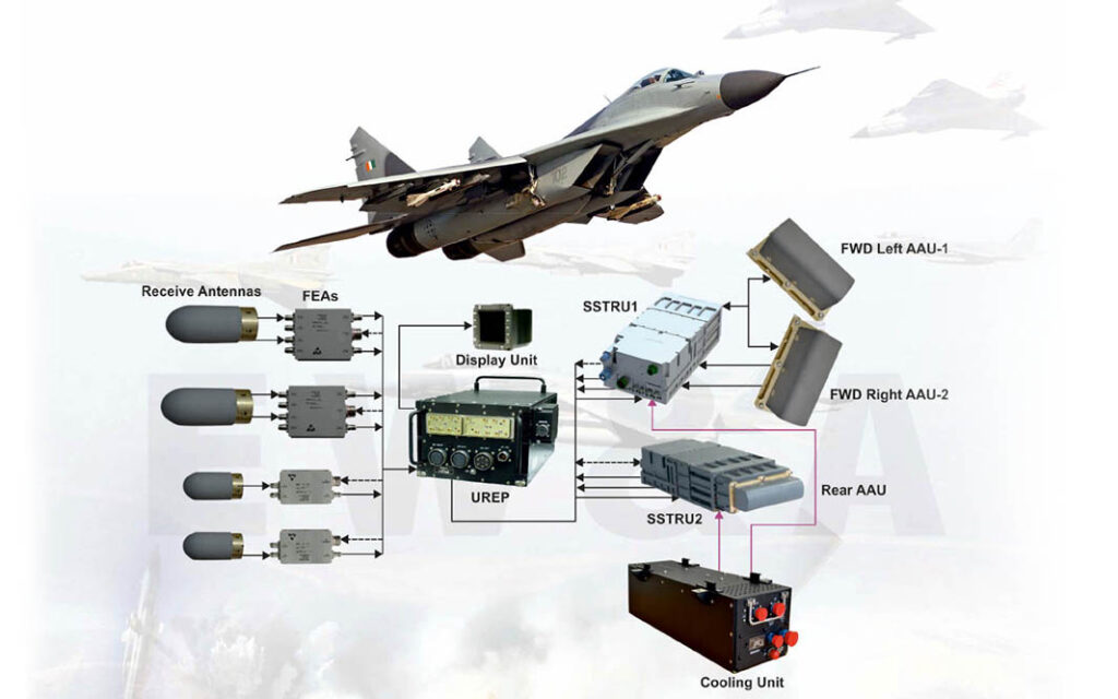
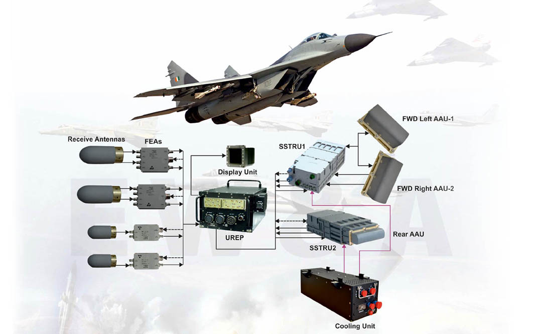
Combat aircraft are not confined to transmitting RF signals – certain signals only need to be received. This is the case for PNT (position, navigation and timing) signals from global navigation satellite system (GNSS) constellations. Additional navigation assistance comes from DME (Distance Measuring Equipment) which receive, and process, data transmitted by VOR (VHF omni-directional range) radio beacons. TACAN (tactical air navigation) is a military-only version of the DME-VOR ensemble. Landing at airfields is greatly assisted by instrument landing systems (ILSs), which provides a safe ‘glide path’ a pilot can follow to land safely. ILS is particularly important when landing in reduced visibility or inclement weather. Furthermore, the ISDS must detect potentially hostile radar signals that may need to be jammed. Threat detection to this end is achieved using a radar warning receiver (RWR). All these disparate systems which send and/or receive RF signals can result in scores of antennas being installed on the aircraft’s fuselage, wings and tail. A fighter pilot informed the author that up to 30 antennas, or more, may equip a contemporary combat aircraft.
Why are so many antennas necessary? You can blame physics. All the aforementioned systems transmit an array of different radio frequencies. For example, the aircraft’s V/UHF radios will use frequencies of between 108 MHz and 137 MHz for radio navigation and ATC communications. Military air-to-air and air-to-ground communications use UHF frequencies of 225 MHz to 400 MHz. A combat aircraft’s radar typically transmits and receives in X-band (8.5 GHz to 10.68 GHz). The UHF radios may also send and receive tactical traffic across UHF Tactical Datalinks (TDLs) like Link-16 (960 MHz to 1.215 GHz). Link-16 is primarily used by NATO and Allied nations to support air operations. Some aircraft may use TDLs like Link-11/22, which mainly supports naval operations, and moves across HF and V/UHF conduits. Civilian ATC and military IFF transponders use frequencies of 1.030 GHz and 1.090 GHz. Aircraft can use several SATCOM frequencies stretching from UHF (399 MHz to 470 MHz) upwards. Combat aircraft must detect and jam radar signals across wavebands of at least 2 GHz to 18 GHz. This waveband is sometimes increased to 40 GHz to encompass radar threats higher up the spectrum. GNSS PNT signals are received on a waveband of 1.1 GHz to 1.6 GHz. VOR signals on frequencies of 962 MHz to 1.150 GHz are received by aircraft DME; aircraft ILS systems receive transmissions of frequencies of 329.3 MHz to 335 MHz, while TACAN uses a waveband of 960 MHz to 1.215 GHz. Last, but not least, radio altimeters use frequencies of 4.2 GHz to 4.4 GHz.
Aircraft, military or civilian, by their very nature regularly cross countries and continents. As such, the radio frequencies they use are guarded by organisations like the International Telecommunications Union (ITU), the specialised UN agency acting as the global custodian of the radio portion of the electromagnetic spectrum.
Pointy bits
All radio-dependent systems need some form of antenna to send and/or receive signals. Several of the systems discussed use blade antennas fitted to the ventral and dorsal portions of an aircraft’s fuselage. Except for HF (which can be ‘bounced’ off the ionosphere, allowing beyond line-of-sight communication), most radio signals operate via line of sight. This means the transmitting and receiving antennas need to ‘see’ each other. The ISDS’s RWRs are usually mounted on the tail of the aircraft and the wingtips. This configuration helps to provide a 360° spherical field-of-view around the plane. There are two issues with antennas: Blade antennas can create drag which can be detrimental to an aircraft’s aerodynamic performance in a small way, but detrimental nonetheless. Aerodynamic performance can also be impinged by the box-like or cylindrical antennas the ISDS depends on for the RWR and ECM.

The other problem with antennas is that they can be good reflectors of radar signals. An aircraft’s visibility to radar is governed by the size of its radar cross section (RCS) and broadly speaking, the smaller the RCS, the harder the aircraft is to detect, identify and track with a radar. Most importantly, a small RCS makes it difficult to guide a SAM or AAM accurately to the plane. RCS is a measure of how much of an incoming radar signal will be reflected to that same radar. The more energy that is reflected, the easier it will be for the radar to follow the aircraft and potentially help cause it harm. Radar signals are reflected well by perpendicular structures like blade antennas; a mirror mounted on a wall will give the best reflection of your face but a mirror canted at a 45° angle will not. Some aircraft, manned or otherwise, and air-launched weapons are designed to have as low an RCS as possible. Their fuselage and surfaces will have smooth curves, or highly angular designs to reflect incoming RF signals away from the transmitting radar antenna. Combat aircraft radars are mounted in the nose and hence usually nicely concealed within an aerodynamic radome.
One size fits all
What if a combat aircraft could have a smaller number of antennas that could do many, if not all, of the functions discussed above? Imagine if the nose-mounted radar antenna could also function as an ECM, RWR, SATCOM terminal, provide V/UHF communications, work as an IFF/ATC interrogator/transponder. Perhaps it could also act as a radio altimeter and receive all the radio navigation signals the aircraft depends on? Aeronautical engineers could make their aircraft as ‘stealthy’ as they like with no need for pointy blade antennas messing up the RCS. All RF signals simply move to and from a multifunction antenna, for instance, one hidden in the aircraft’s aerodynamic nose; not only will RCS be reduced, but aircraft performance will improve helping save fuel, extend range and probably improving manoeuvrability.
Some advancements have already been made to this end. Leonardo’s ECRS Mk.2 radar will equip the Royal Air Force’s Eurofighter Typhoon F/GR4 Tranche-3 jets, according to the UK’s Ministry of Defence. Not only will the ECRS Mk.2 perform all the functions one would expect of a combat aircraft radar, including air and surface search and tracking, but it can also work as an ECM system against radar threats. That the ECRS Mk.2 uses an active electronically scanned array (AESA) radar design helps immensely in this regard. A whole article could be dedicated to AESA design but to summarise, these are mounted with hundreds, if not thousands, of transmit/receive modules (TRMs) comprising the antenna array. Each TRM is effectively a miniature radar. The module generates the RF signal, modulates and transmits the signal and receives the reflection. The TRMs can electronically steer their transmissions in a particular direction to look towards the surface, for example. The multitude of TRMs means the pilot can task the radar to do several tasks simultaneously or in quick succession. Some TRMs may be looking upwards for potential targets, some may be looking downwards for the same reason. Other modules may be transmitting a jamming signal against a radar-guided AAM.

Why is this already impressive radar not performing additional functions beyond traditional radar tasks and jamming? RF engineering is advancing the multifunction antenna, but it is still some years away. Part of the problem is that the RF signals discussed above do different things and hence use different waveforms. A family station wagon, a four-wheel drive and a rally car all take people from one place to another. Nonetheless, these vehicles are vastly different in design and performance, something that is also the case for these waveforms and their antennas. Furthermore, antennas must have a size proportionate to the signals they handle. A basic RF rule of thumb is that antennas must be between one-half and one-quarter length of the frequencies they handle. Therefore, a VHF frequency of 225 MHz has a wavelength of 133.4 cm meaning that the antenna will need to be between 66.62 cm and 33.31 cm in length. A TACAN receiving antenna will need to be between 15.61 cm and 7.87 cm long for frequencies of 960 MHz, and between 12.34 cm and 6.17 cm for TACAN’s 1.215 GHz signals. Another factor altering antenna design is desired gain; gain is a measure of an antenna’s ability to focus an RF signal in a particular direction and is measured in dB. The better an antenna’s gain, the sharper the focus shall be. Gain is the result of the antenna’s physical design, and how powerful a signal the radio or radar can generate.
Current efforts
Germany’s Fraunhofer Institute is one organisation heavily involved in the realisation of this multifunction antenna holy grail. The author was recently briefed on some of the interesting work it is doing in this regard. Using the analogy of a smartphone or Swiss Army knife, researchers from the institute defined a multifunction system as a single architecture performing multiple tasks. A key attraction of a multifunction antenna, particularly in the airpower domain, is that it would weigh less compared to several disparate systems. Likewise, a single antenna performing multiple functions may cost less to procure and support compared those conventional, disparate systems. There may be further weight and cost reductions if a multifunction antenna works with a common ‘back end’, which contains all the hardware and software needed for processing incoming and outgoing RF signals. Combat aircraft and unmanned aerial vehicles (UAVs) remain the most likely platforms for the initial future uptake of multifunction antenna technology. This makes sense as both are size, weight and power (SWaP)-constrained platforms.
Initial plans call for the development of multifunction antenna technologies to support radar, communications and ISDS tasks. The researchers are currently thinking about systems that would cover an ultra-wide waveband of 5 to 18 GHz which, as readers will note, would already encompass some of the systems discussed above. However, working with such a wide waveband requires novel approaches to antenna design due to the frequency and gain strictures discussed above. Metamaterials, which the author has discussed in previous ESD articles, offer promise. Space here is insufficient to describe metamaterials in detail; however, to summarise, they can be designed to transmit or receive certain frequencies, but not others, effectively acting as an RF filter. Other requirements include transmit and receive hardware to handle signals across this considerable waveband.
Consider the following with regard to the complexity of multifunction antenna design: The Fraunhofer Institute researchers noted that radars like to generate a highly-focused signal that can be steered precisely in a specific direction. ISDS RWRs like to hear potentially very weak signals coming from any direction. This is because radar threats will try to be as discreet as possible to avoid detection, and a threat can emanate from any vector. While radars must send out a signal and listen for the reflection, RWRs do not need to transmit, just listen. To further complicate matters, a radar will transmit and receive its signals in X-band. The RWR will have to monitor a much wider waveband of potential threats because the ISDS must be ready to counter numerous threats across a range of frequencies. Radar signals can be very ‘loud’ i.e., relatively strong when they leave the radar. This strength may momentarily block out other X-band signals on the same frequency the RWR needs to detect. Nonetheless, for a multifunction antenna to be effective it must do simultaneous threat and target tracking.

Some of Fraunhofer’s endeavours are focusing on the realisation of ultra-wideband receivers working in the 5 to 18 GHz waveband. The researchers are also perfecting techniques to prevent the injection of strong outward signals into RF receivers. Allied to this is ensuring the electromagnetic compatibility of the multifunction antenna’s respective functions. In short, all the disparate capabilities (radar, communications and ISDS functions etc.) must ‘play nice’ – a challenge made more vexing given how RF signals behave. An outgoing transmission will cause additional (but progressively weakening) signals in ‘harmonic’ frequencies. For example, a 5 GHz transmission will create 10 GHz and 15 GHz harmonic signals. These could cause interference for an RWR also monitoring these latter frequencies.
The institute is taking some important steps forward in realising true multifunction antennas. Systems like the ECRS Mk.2 are blazing a trail, but are still relatively limited, performing only two tasks, radar and ECM. It seems likely that true multifunction antennas are some years from routine use on military aircraft and UAVs. Fraunhofer’s work in advancing this discipline will play a major role in perfecting this technology.
We may see such antennas on platforms such as the Franco-German 6th-Gen Système de Combat Aérien du Futur (SCAF), an aircraft that is expected to begin entering service during the first half of the 2030s, according to reports. Multifunction antennas will help in no small measure to improve the aircraft’s performance and reduce RCS. Advancements in metamaterials may mean such antennas can be mounted conformally on the aircraft’s skin to ensure a degree of redundancy. Other antennas on the aircraft can pick up the slack should one become unserviceable. Additional, conformal antennas, would provide additional lines-of-sight across which to send and receive RF signals. Although 5th-Gen and some upgraded 4th-Gen aircraft have already made great strides in this area, it may only be a matter of years until pointy, disparate antennas become a thing of the past in combat aircraft design.
Dr Thomas Withington
Author: Dr Thomas Withington is an independent electronic warfare, radar and military communications specialist based in France.


